Knowledge Base
How to Install an Internal Battery into the C22 and H24x
Published: March 24, 2015
Updated: October 4, 2017
Installing an internal battery in the Cybermed C22, iOne C22, or iOne H24x is a fairly simple process and only requires a minimum preparation and tools. To prepare for this project, you will want a large flat work space, which is clean of all debris. We recommend putting down a layer of bubble wrap to further protect the touch glass which will go face down on the work bench.Updated: October 4, 2017
Tools needed for the project are very simple. You will want a medium sized Phillips screwdriver, a paperclip and a very small flathead screwdriver or pocket knife.
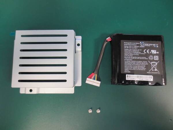
In the packaging, you will find the battery, the battery bracket and two screws.
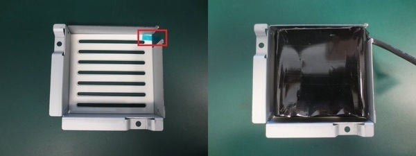
To keep the battery from moving around, we will attach it to the inside of the bracket. To do this, pull up on the clear blue tab in the upper corner. This will expose the double sided sticky tape. Now place the battery into the bracket sticker side down.
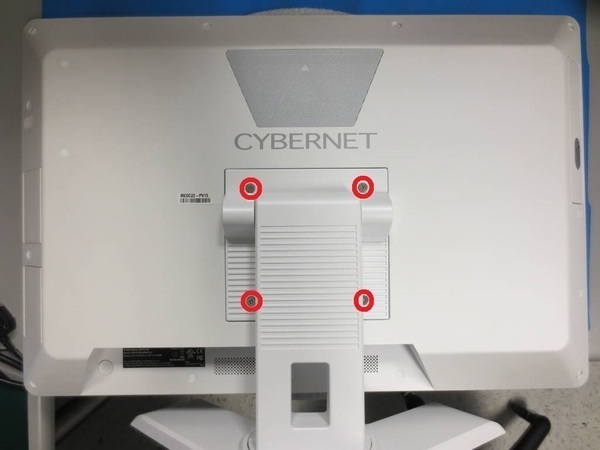
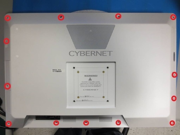
With the battery secured, we need to open the unit. First remove the base (if it came with a base). If no base stand, there may be an mounting bracket, which would need to be removed. This is done by removing the 4 large VESA mounting screws. located at the 4 circles.
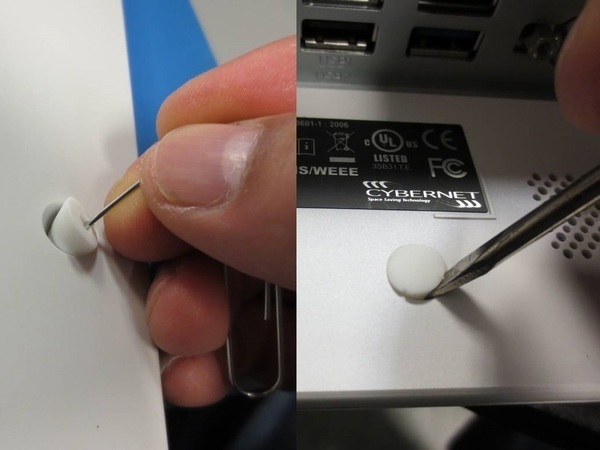
Both the C22 and H24x have rubber screw covers. There are two types. There are angled larger covers on the sides and top and some smaller flat covers at the bottom. To remove the angled covers, use a paperclip and pull them out using the hole in the middle. The smaller flat covers can be pulled out using a small flathead screwdriver or pocket knife.
Now we will remove the large rear plastic housing. Remove the screws from around the edge of the housing using your Phillips screwdriver.
Once these screws are removed, we just need to lift the cover off the unit. The only time you would have an issue here is if you have any other options installed, such as a SmartCard reader or an optical drive. In the event either of these options are in place, there will be cables that connect the option to the unit, so take care with those cables and disconnect where needed. For an optical drive, use a paperclip to eject the door. Lift up the little grey rubber button cover and press the eject button using the small hole. Then lift the left side of the rear housing and angle it, so it can slide over the optical drive door.
IMPORTANT: If your unit has an optical drive, it must removed before you install the internal battery. There is not enough space to have both an optical drive and an internal battery. To remove the optical drive, remove the four screw holding the bracket and disconnect the SATA and power cables form the motherboard. Detach the optical drive door cover and use double sided tape to secure it as a blanking plate.
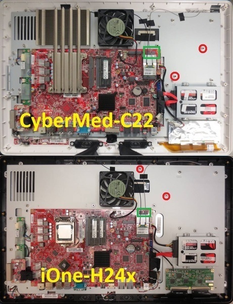
Finally, we will remove the internal metal cage. You can do this by removing all of the screws that aim downward around the edge of the metal cage, marked with circles. To remove the metal cage, lift the top edge of it and slide it downward off the I/O ports.
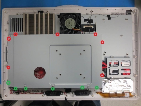
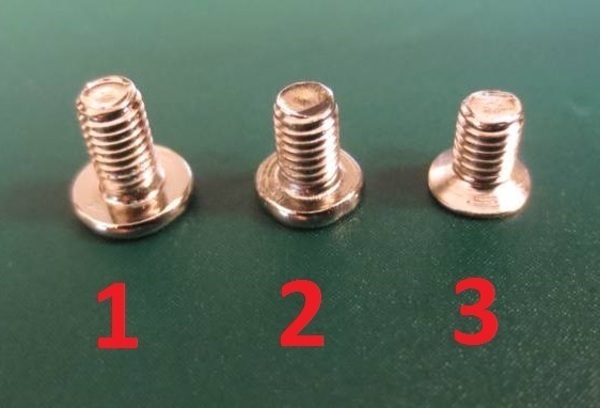
You will see two different colored circles on the last image, this is due to the screws being different types. You will need to make sure the correct screws go back when you are finished. You can see in the image below, that there are three different kinds of screws used. The larger topped screw marked with a "1" below are for the rear plastic cover. The middle smaller head screw is for the top and sides of the metal cage. The last screw is counter-sunk and is used for the lower edge of the metal cage.
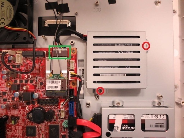
Now we are ready to install our battery. In the photos below, you will see the posts the battery bracket screws down to circled in red. The connector on the motherboard, where the battery plugs in has a green rectangle around it in the upper right corner of the motherboard.
When you are done, your unit will look like the image below.
The only thing left now is to reverse the steps to open the unit. Start by replacing the metal cage. Hook the bottom on the I/O ports and lay it flat, being careful of the new battery cable and screw it down. Now replace the rear plastic housing, screw it down and replace the rubber covers. Now replace the base or mounting bracket.